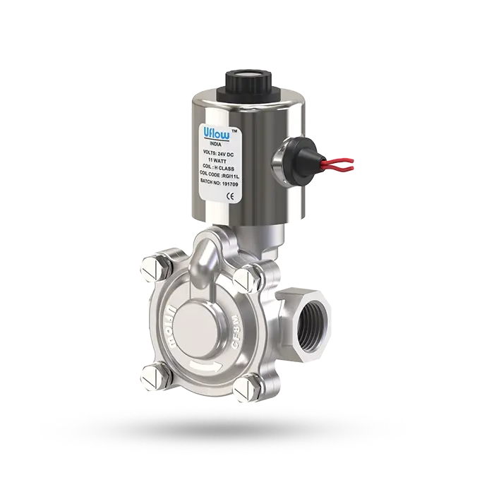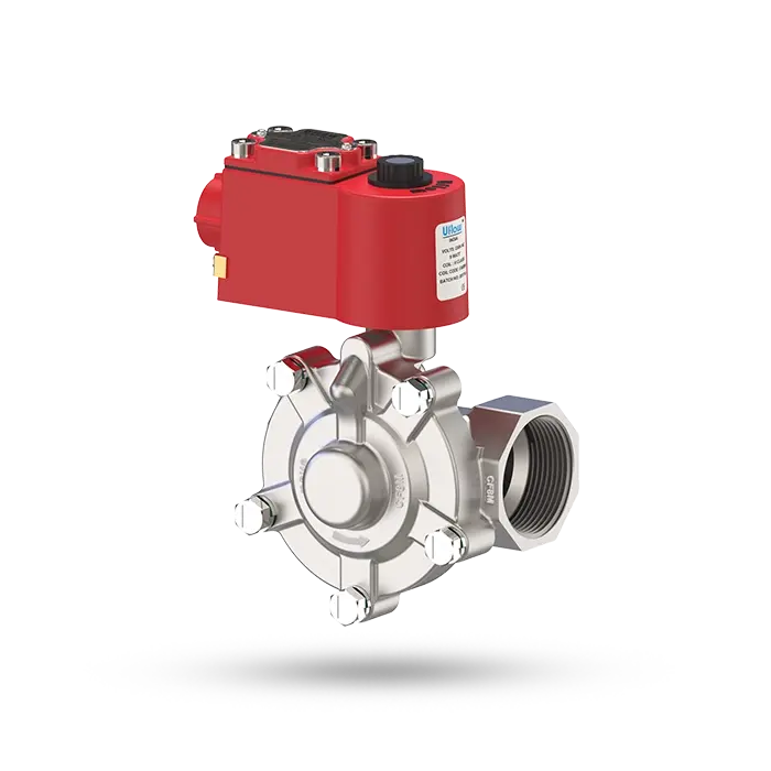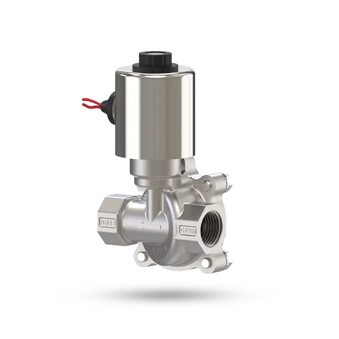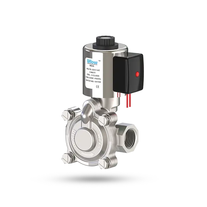


Refer below technical data sheet (Available BSP / NPT)
Screwed / Flange
SS ASTM A351 Grade CF8 / CF8M
| Nitrile (NBR) | EPDM | Viton (FKM) |
| -30° C to 90° C | -10° C to 140° C | -10° C to 180° C |
-10° C to 70° C
Air, Water, Chemical, Gas, Oil, Diesel, Kerosene, LPG.
Internal Parts are in superior corrosion resistance steel, (Equivalent to SS316L) Suitable for Food Industries, Pharmaceuticals, Chemical application & Highly corrosive environment
| 24AC | 110AC | 230AC | 12DC | 24DC |
| 9W | 9W | 9W | 10W | 11W |
90% Power saver series also available, Manual Override, Water hammering reducer also available to avoid water hammer forces.
Available on Request. - High Pressure 20Kg Series. - Manual Override
High Reliability Unaffected by Voltage Surges. Easy coil changes coil lockable in 4X90 position, or freely movable in between as require.
Epoxy square coil, Metallic round enclosure, IP-68 Weatherproof enclosure.
Use of filter in the inlet port is recommended.


| Model No. | Body Material | Pipe (Inch) | Orifice (mm) | Min. Operating Pressure Kg/cm² | Max. Operating Pressure Kg/cm² | Seal & Diaphragm Material | Flow Factor Kv m³ / hr |
|---|---|---|---|---|---|---|---|
| PCN-7E | CF8 / CF8M | ⅜” | 15 | 0.5 | 12 | NBR / EPDM / VITON | 2 |
| PCN-2E | CF8 / CF8M | ½” | 17 | 0.5 | 12 | NBR / EPDM / VITON | 4.4 |
| PCN-3E | CF8 / CF8M | ¾” | 20 | 0.5 | 12 | NBR / EPDM / VITON | 3.7 |
| PCN-4E | CF8 / CF8M | 1” | 25 | 0.5 | 12 | NBR / EPDM / VITON | 10 |
| PCN-5E | CF8 / CF8M | 1¼” | 36 | 0.5 | 12 | NBR / EPDM / VITON | 12.2 |
| PCN-6E | CF8 / CF8M | 1½” | 36 | 0.5 | 12 | NBR / EPDM / VITON | 17.1 |
| PCN-8E | CF8 / CF8M | 2” | 47 | 0.5 | 12 | NBR / EPDM / VITON | 33.3 |
| PCN-9E | CF8 / CF8M | 2½” | 59 | 0.5 | 12 | NBR / EPDM / VITON | 43.5 |
| PCN-AE | CF8 / CF8M | 3” | 71 | 0.5 | 12 | NBR / EPDM / VITON | 64.5 |
| PCN-BI | CF8 / CF8M | 4” | 98 | 0.5 | 12 | NBR / EPDM / VITON | 115 |

All Dimensions are approx
| Model No. | Port Size | Diagram No. | A | B | C | D | E | F |
|---|---|---|---|---|---|---|---|---|
| PCN-7E | ⅜” | 16.1 | 67 | 123 | 95 | 52 | 38 | 49 |
| PCN-2E | ½” | 16.1 | 67 | 123 | 95 | 52 | 38 | 49 |
| PCN-3E | ¾” | 16.1 | 81 | 130 | 97 | 60 | 38 | 49 |
| PCN-4E | 1” | 16.1 | 96 | 146 | 105 | 66 | 38 | 49 |
| PCN-5E | 1¼” | 16.1 | 108 | 154 | 108 | 88 | 38 | 49 |
| PCN-6E | 1½” | 16.1 | 108 | 154 | 108 | 88 | 38 | 49 |
| PCN-8E | 2” | 16.1 | 132 | 181 | 126 | 102 | 38 | 49 |
| PCN-9E | 2½” | 16.1 | 166 | 212 | 140 | 126 | 38 | 49 |
| PCN-AE | 3” | 16.1 | 192 | 237 | 151 | 138 | 38 | 49 |
| PCN-BI | 4” | 16.1 | 262 | 257 | 194 | 202 | 50 | 63 |
Note: In normally open valve dimension B&C will increase up to 8mm.

