TEMPERATURE Range
| NBR | -20°C to +80°C |
| Viton | -20°C to +125°C |
| Flourosilicone | -60°C to +110°C |
END STROKE (0° - 90°)
| +5° Over travelling Possible for opening |
| -5° Under travelling Can be adjusted |
WORKING PRESSURE
Maximum working pressure 8 bar
AIR CONSUMPTION COMPARISON WITH OTHER REPUTED BRAND
| Model | Piston Inward Stroke ml / bar | Piston Outward Stroke ml / bar |
| (Uflow) AD-50 | 128 | 137 |
| Other Brand Y | 260 | 110 |
| Other Brand X | 200 | 180 |
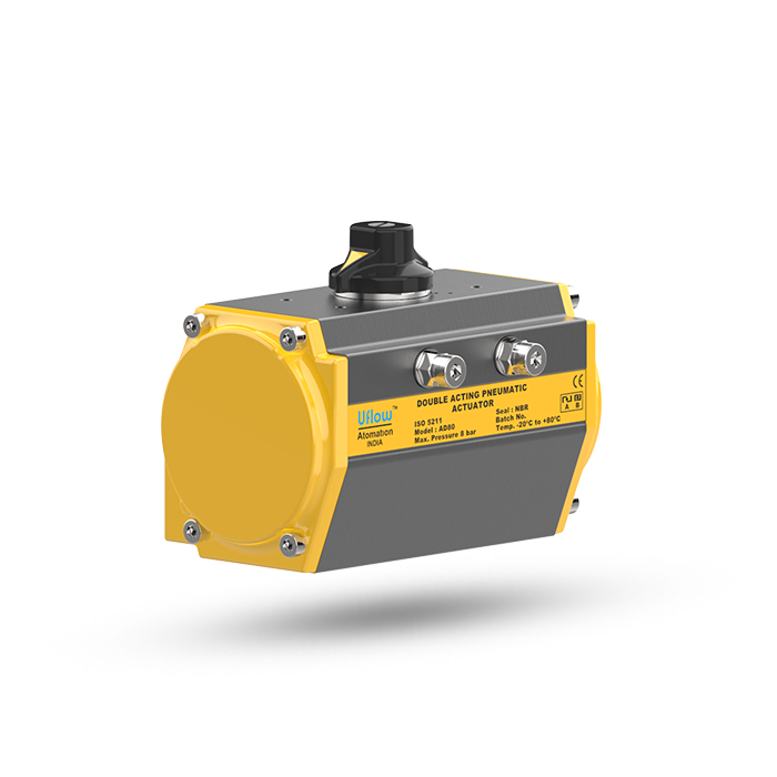
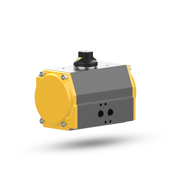
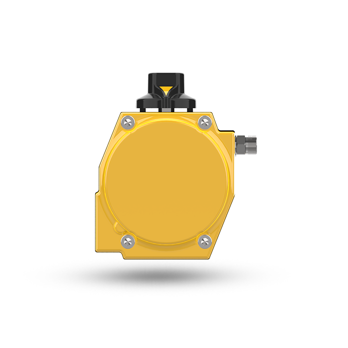
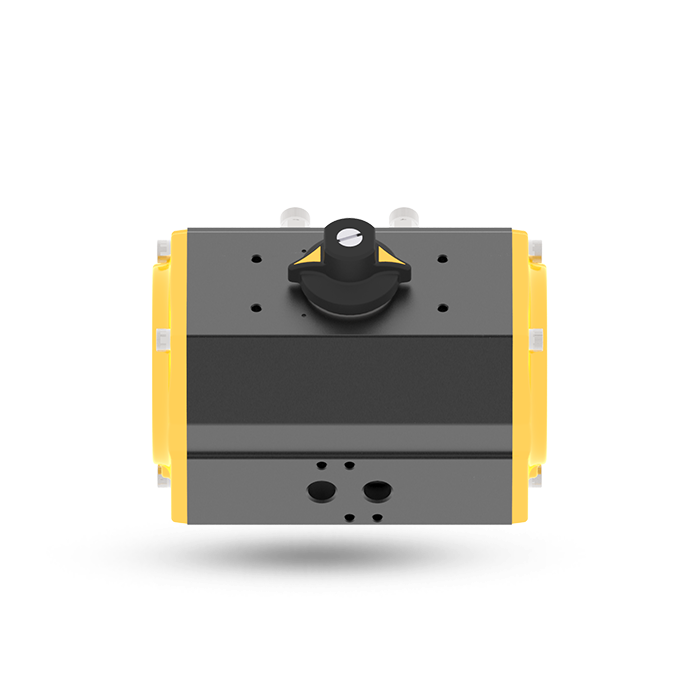
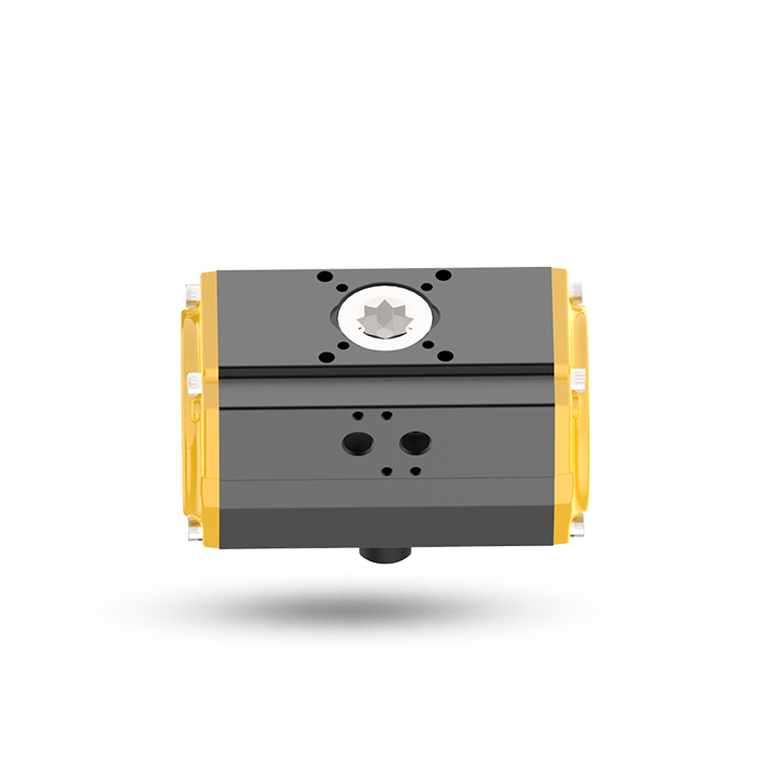
Uflow has successfully developed Compact, Patented Aluminium Free Rack & Pinion Pneumatic Rotary Actuator, Consuming Low Volume of Air.
- Wear proof aluminium free Rack & Pinion design.
- Low air consumption with maximum torque due to the compact design.
- Providing a hard-anodized body for high corrosion resistance.
- Smooth travelling stroke for extending the life of ball valve sheet.
- Finer teeth module for smoother operation, and jerk-free sliding.
- Maintenance-free design.
- Aluminium Extruded, Hard Anodized Body.
- Design Standard : ISO 5211
- Approved as per ATEX
| Model No. | Diagram No. | 2 Bar | 3 Bar | 4 Bar | 5 Bar | 6 Bar | 7 Bar | 8 Bar | Piston Inward Stroke, ml/bar |
Piston Outward Stroke, ml/bar |
|---|---|---|---|---|---|---|---|---|---|---|
| AD-32V2 | 4.1 | 3 | 5 | 6 | 8 | 9 | 11 | 12 | 36 | 40 |
| AD-40V2 | 4.1 | 7 | 10 | 14 | 17 | 21 | 24 | 28 | 83 | 104 |
| AD-50V2 | 4.1 | 11 | 16 | 22 | 27 | 32.5 | 38 | 43 | 128 | 137 |
| AD-63V2 | 4.1 | 20 | 30 | 40 | 50 | 60 | 70 | 80 | 210 | 280 |
| AD-80V2 | 4.1 | 35 | 52 | 69 | 87 | 103 | 121 | 138 | 360 | 450 |
| AD-90V2 | 4.1 | 51 | 76 | 102 | 127 | 153 | 178 | 204 | 522 | 768 |
| AD-100V2 | 4.1 | 73 | 110 | 146 | 183 | 220 | 256 | 293 | 780 | 1040 |
| AD-110V2 | 4.1 | 90 | 135 | 180 | 225 | 270 | 315 | 360 | 966 | 1325 |
| AD-125V2 | 4.1 | 127 | 190 | 254 | 318 | 381 | 446 | 508 | 2800 | 1810 |
| AD-150V2 | 4.1 | 210 | 316 | 421 | 526 | 631 | 737 | 842 | 5390 | 3150 |
| AD-175V2 | 4.1 | 300 | 450 | 600 | 750 | 900 | 1050 | 1200 | 7525 | 4720 |
| AD-200V2 | 4.1 | 456 | 684 | 912 | 1140 | 1368 | 1596 | 1824 | 11980 | 7780 |
| AD-250V2 | 4.1 | 741 | 1111 | 1482 | 1852 | 2223 | 2593 | 2964 | 14870 | 12145 |
| AD-300V2 | 4.1 | 1125 | 1688 | 2251 | 2813 | 3376 | 3939 | 4502 | 37175 | 19630 |
| AD-350V2 | 4.1 | 1540 | 2310 | 3080 | 3850 | 4620 | 5390 | 6160 | 40535 | 26430 |

| Model No. | Diagram No. | A | B | C | D | F | G | I | J | K | L | M | N | O | P | N1 | O1 | P1 | CH 90 | ISO FLANGE |
|---|---|---|---|---|---|---|---|---|---|---|---|---|---|---|---|---|---|---|---|---|
| AD-32V2 | 4.1 | 92 | 48 | 20 | 54 | 30 | 50 | 10 | 4 | 16 | 12 | ¹⁄₈” | M5 | 09 | 36 | - | - | - | 09 | F03 |
| AD-40V2 | 4.1 | 129 | 66 | 20 | 64 | 30 | 80 | 13 | 4 | 16 | 12 | ¼” | M6 | 12 | 50 | M5 | 10 | 36 | 11 | F03/F05 |
| AD-50V2 | 4.1 | 125 | 77 | 20 | 72 | 30 | 80 | 13 | 4 | 16 | 12 | ¼” | M6 | 12 | 50 | M5 | 10 | 36 | 11 | F03/F05 |
| AD-63V2 | 4.1 | 147 | 87 | 20 | 86 | 30 | 80 | 15 | 4 | 16 | 12 | ¼” | M8 | 12 | 70 | M6 | 10 | 50 | 14 | F05/F07 |
| AD-80V2 | 4.1 | 170 | 103 | 20 | 98 | 30 | 80 | 18 | 4 | 16 | 12 | ¼” | M8 | 12 | 70 | M6 | 10 | 50 | 17 | F05/F07 |
| AD-90V2 | 4.1 | 198 | 115 | 20 | 110 | 30 | 80 | 22 | 4 | 16 | 12 | ¼” | M8 | 12 | 70 | - | - | - | 17 | F07 |
| AD-100V2 | 4.1 | 220 | 129 | 20 | 126 | 30 | 80 | 26 | 4 | 16 | 12 | ¼” | M10 | 15 | 102 | M8 | 14 | 70 | 22 | F07/F10 |
| AD-110V2 | 4.1 | 231 | 136 | 20 | 131 | 30 | 80 | 30 | 4 | 16 | 12 | ¼” | M10 | 15 | 102 | M8 | 14 | 70 | 22 | F07/F10 |
| AD-125V2 | 4.1 | 389 | 161 | 20 | 146 | 30 | 80 | 30 | 4 | 16 | 12 | ¼” | M12 | 20 | 125 | M10 | 14 | 102 | 22 | F10/F12 |
| AD-150V2 | 4.1 | 465 | 193 | 20 | 175 | 30 | 80 | 36 | 4 | 16 | 12 | ¼” | M12 | 20 | 125 | M10 | 14 | 102 | 27 | F10/F12 |
| AD-175V2 | 4.1 | 500 | 212 | 20.5 | 195 | 30 | 80 | 41 | 4 | 16 | 12 | ¼” | M12 | 20 | 125 | M10 | 20 | 102 | 27 | F10/F12 |
| AD-200V2 | 4.1 | 552 | 255 | 30 | 288 | 30 | 130 | 41 | 4 | 16 | 12 | ¼” | M16 | 24 | 140 | M10 | 15 | 102 | 36 | F10/F14 |
| AD-250V2 | 4.1 | 723 | 255 | 30 | 288 | 30 | 130 | 41 | 4 | 16 | 12 | ¼” | M16 | 24 | 140 | - | - | - | 46 | F14 |
| AD-300V2 | 4.1 | 755 | 360 | 30 | 390 | 30 | 130 | 41 | 4 | 22.5 | 20 | ¹⁄2" | M20 | 30 | 165 | - | - | - | 46 | F16 |
| AD-350V2 | 4.1 | 865 | 360 | 30 | 390 | 30 | 130 | 41 | 4 | 22.5 | 20 | ¹⁄2" | M20 | 30 | 165 | - | - | - | 55 | F16 |

